

The standard Arduino Uno Development Board is the world's most popular tool for electronics beginners and engineering students. But have you ever wondered what goes on inside the board—or how you can build one yourself from scratch on a breadboard or custom PCB?
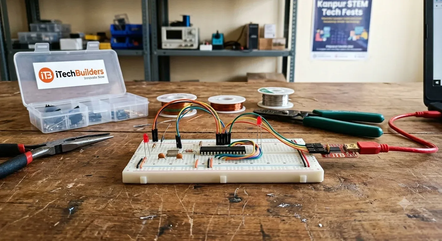
At iTechBuilders.com in #KanpurTech, we believe that understanding the minimal operating circuit of a microcontroller is the single most valuable step toward mastering #EmbeddedSystems and custom PCB design. In this step-by-step guide, we will turn a standalone 28-pin Microchip ATmega328P-PU DIP IC into a fully operational Arduino Uno on a solderless breadboard.
Why Build a Standalone Arduino on a Breadboard?
- Cost Efficiency: A standalone chip and minimal supporting passive components cost significantly less than a full dev board, making it perfect for embedding directly into final products.
- Power Efficiency: Commercial Arduino boards carry power-hungry LEDs and voltage regulators that consume power continuously. A bare-bones circuit consumes microamps in deep sleep mode.
- Custom PCB Manufacturing: Once you understand the minimal circuit schematic, you can design custom, professional PCB shields for your robotics and #IoTKanpur prototypes.
Required Components List
You can purchase every component required for this build directly from our iTechBuilders Electronics Store in Kanpur:
- ATmega328P-PU Microcontroller IC (28-pin DIP)
- 16 MHz Crystal Oscillator
- 2x 22pF Ceramic Capacitors
- 10k Ohm Resistor (Pull-up for RESET pin)
- 220 Ohm Resistor (Current limiting for LED)
- 5mm LED (Pin 13 status LED)
- 0.1 µF Ceramic Capacitor (For auto-reset FTDI line)
- 7805 5V Voltage Regulator IC + 10µF Electrolytic Capacitors (For power regulation)
- FTDI USB-to-TTL Serial Adapter Module (For uploading code)
- Solderless Breadboard & Jumper Wire Set
ATmega328P Pinout vs. Arduino Digital/Analog Pin Mapping
Before making connections, it is essential to map the physical DIP-28 IC pins of the ATmega328P to the corresponding digital and analog pin designations used in the Arduino IDE:
                     ATmega328P-PU DIP-28 PINOUT MAPPING

                           ┌───────────┬───────────┐
      RESET (PC6) ─────────┤ 1       28├─── PC5 (ADC5 / SCL / A5)
 RX / D0 (PD0) ────────────┤ 2       27├─── PC4 (ADC4 / SDA / A4)
 TX / D1 (PD1) ────────────┤ 3       26├─── PC3 (ADC3 / A3)
      D2 (PD2) ────────────┤ 4       25├─── PC2 (ADC2 / A2)
 PWM  D3 (PD3) ────────────┤ 5       24├─── PC1 (ADC1 / A1)
      D4 (PD4) ────────────┤ 6       23├─── PC0 (ADC0 / A0)
           VCC ────────────┤ 7       22├─── GND
           GND ────────────┤ 8       21├─── AREF (Analog Reference)
          XTAL1 ───────────┤ 9       20├─── AVCC (+5V Power)
          XTAL2 ───────────┤ 10      19├─── PB5 (D13 / Built-in LED)
 PWM  D5 (PD5) ────────────┤ 11      18├─── PB4 (D12 / MISO)
 PWM  D6 (PD6) ────────────┤ 12      17├─── PB3 (D11 / MOSI / PWM)
      D7 (PD7) ────────────┤ 13      16├─── PB2 (D10 / SS / PWM)
      D8 (PB0) ────────────┤ 14      15├─── PB1 (D9 / PWM)
                           └───────────┴───────────┘
Step-by-Step Circuit Assembly
1. Power & Ground Connections
- Place the ATmega328P IC spanning across the center divider of your breadboard.
- Connect Pin 7 (VCC) and Pin 20 (AVCC) to the positive (+5V) power rail.
- Connect Pin 8 (GND) and Pin 22 (GND) to the ground rail.
2. Master Reset Circuit
- Connect a 10kΩ pull-up resistor from Pin 1 (RESET) to the +5V rail. This prevents the chip from constantly resetting due to floating noise.
- Optionally add a tactile push button connected between Pin 1 and GND to serve as a manual reset button.
3. External 16 MHz Clock Circuit
- Connect the two pins of the 16 MHz crystal oscillator across Pin 9 (XTAL1) and Pin 10 (XTAL2).
- Connect one 22pF ceramic capacitor from Pin 9 to Ground, and the second 22pF ceramic capacitor from Pin 10 to Ground.
4. Status LED (Pin 13)
- Connect the anode (longer leg) of a 5mm LED to Pin 19 (Arduino Digital Pin 13).
- Connect the cathode through a 220Ω resistor to Ground.
                        MINIMAL BAREBONES ARDUINO CIRCUIT

         +5V ───[ 10k Ω ]───┬─── Pin 1 (RESET)
                            │
                       [ 0.1µF ] ─── FTDI DTR Pin (For Auto Reset)

     Pin 9 (XTAL1) ───┬───[ 16 MHz Crystal ]───┬─── Pin 10 (XTAL2)
                      │                        │
                   [ 22pF ]                 [ 22pF ]
                      │                        │
                     GND                      GND
How to Burn the Arduino Bootloader
If your ATmega328P chip is brand new from the factory, it will not have the Arduino bootloader pre-installed. You can turn any standard Arduino Uno R3 into an In-System Programmer (ISP) to flash the bootloader onto your breadboard chip:
- Connect your standard Arduino Uno board to your computer. Open Arduino IDE, select File > Examples > 11.ArduinoISP > ArduinoISP, and upload it to your board.
- Wire the standard Arduino to your breadboard chip as follows:
- Arduino D10 ➔ Breadboard ATmega328P Pin 1 (RESET)
- Arduino D11 (MOSI) ➔ Breadboard ATmega328P Pin 17 (MOSI)
- Arduino D12 (MISO) ➔ Breadboard ATmega328P Pin 18 (MISO)
- Arduino D13 (SCK) ➔ Breadboard ATmega328P Pin 19 (SCK)
- Arduino 5V & GND ➔ Breadboard 5V & GND rails
- In Arduino IDE, select Tools > Board > Arduino Uno.
- Select Tools > Programmer > Arduino as ISP.
- Click Tools > Burn Bootloader. You will see the RX/TX LEDs flash, and the IDE will report "Done burning bootloader"!
Uploading Code via FTDI Serial Adapter
Once the bootloader is installed, you can program your standalone board over USB using an FTDI USB-to-TTL Serial Module:
- FTDI VCC (5V) ➔ Breadboard +5V Rail
- FTDI GND ➔ Breadboard GND Rail
- FTDI TXD ➔ ATmega328P Pin 2 (RXD / D0)
- FTDI RXD ➔ ATmega328P Pin 3 (TXD / D1)
- FTDI DTR ➔ 0.1µF Capacitor ➔ ATmega328P Pin 1 (RESET)
Open the standard Blink example in Arduino IDE, select the target COM port, and press Upload. The LED on Pin 19 will begin blinking steadily every second!
Build Your Custom Embedded Hardware Projects with iTechBuilders
Mastering bare-bones microcontroller design opens up endless possibilities for custom product manufacturing, robotics, and commercial IoT automation in #ElectronicsStoreKanpur.
Get original ATmega328P microcontrollers, IC sockets, crystal oscillators, and prototyping accessories delivered directly to your doorstep from our local store in Kanpur.
Shop Component Kits at iTechBuilders Now
Comments
0