
Learn how to build a multi-channel WiFi smart home switch using an ESP32, relay modules, and optocouplers—complete with physical switch overrides and high-voltage safety practices.
A step-by-step maker guide to designing a multi-channel smart home relay switch featuring local web server hosting, optocoupler mains isolation, physical manual switch overrides, and low-cost component integration.
Smart home automation systems have revolutionized how we control lights, fans, and household appliances. However, commercial smart switches are often expensive, require proprietary hubs, or depend entirely on cloud services that can lag or fail when internet connections drop. By building your own smart switch using an ESP32 Development Board | Doit DevKit V1 | powerful Wroom32 module, you can create a local, ultra-responsive 4-channel switching unit controlled via smartphone or web browser—all while retaining traditional wall switch overrides for your family members.
| Core System Parameter | Detailed Engineering Specification & Implementation |
|---|---|
| Primary Controller | ESP32 Development Board running an asynchronous web server for instant wireless switching. |
| High Voltage Switching | 4-Channel Relay Module equipped with optocoupler IC isolation to protect low-voltage microcontrollers from AC voltage spikes. |
| Embedded Power Conversion | Hi-Link AC-DC Step-Down Power Supply Module (220V AC to 5V DC) for compact wall-box installation. |
| Control Modes | Dual operation mode: Wireless web app control combined with physical toggle switch manual override. |
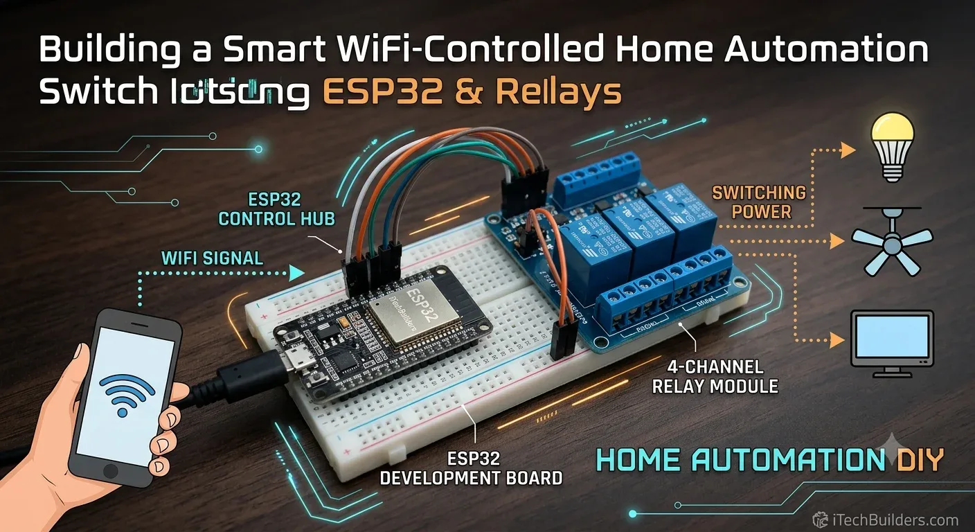
The custom ESP32 smart switch operates locally over your home's Wi-Fi network without requiring third-party cloud servers. Here is a breakdown of how the hardware layers communicate:
| Stage | Subsystem | Operational Functionality |
|---|---|---|
| 1. Command Reception | Local Web Server / WebSockets | The ESP32 hosts a lightweight web page on its local IP address. Toggling a button on your phone dispatches an instant HTTP request or WebSocket packet to the controller. |
| 2. Logic & Override Check | ESP32 WROOM32 Core | The dual-core processor evaluates both incoming Wi-Fi requests and state changes from physical wall switches, maintaining bidirectional state sync. |
| 3. Galvanic Signal Isolation | Optocoupler Modules | Optocouplers transmit control signals using light internally, completely isolating the ESP32's 3.3V logic circuit from high-voltage AC electrical noise and back-EMF. |
| 4. Load Actuation | 4-Channel Relay Board | Electromechanical relays open or close high-voltage AC lines (up to 250V AC / 10A) to power lights, fans, or socket channels. |
Build your smart home switch reliably by sourcing genuine components directly from iTechBuilders:
| Component Category | Specific Part & Purpose | Official iTechBuilders Store Link |
|---|---|---|
| 1. Microcontroller | ESP32 DevKit V1 for Wi-Fi stack & GPIO switching. | ESP32 Development Board | Doit DevKit V1 |
| 2. Relay Actuator | 4-Channel 5V Relay Module with Optocoupler Isolation. | 1-Channel / Multi-Channel 5V Relay Module |
| 3. Power Conversion | Compact Hi-Link 220V AC to 5V DC Step-Down Power Supply Module. | Buck Converter / Power Supply Modules |
| 4. Prototyping Tools | Hot glue gun for securing internal modules inside switchboxes. | Glue Gun with Free Glue Sticks |

Comments
0