
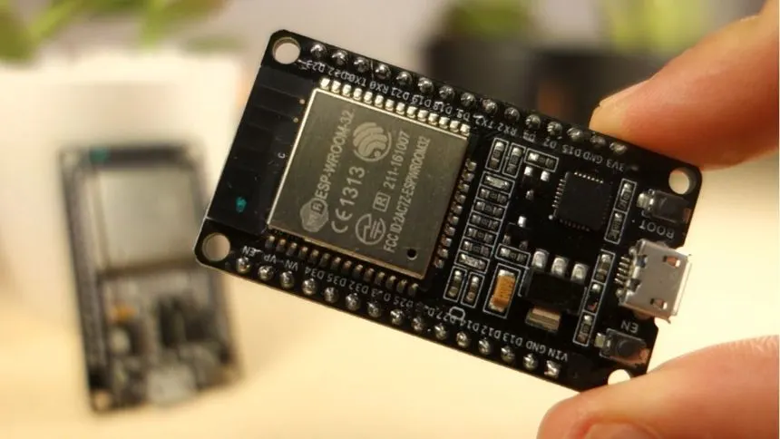
Master the ESP32 pinout with this definitive guide. Learn the functions of each GPIO, including ADC, DAC, I2C, SPI, and touch sensors. Avoid common mistakes with strapping pins and get practical code examples for your next IoT project. Perfect for beginners and advanced users.
The ESP32 is a powerful, feature-rich microcontroller that has become a cornerstone of IoT and wireless projects. But with its complex dual-core processor and multitude of pins, it can be intimidating for beginners and experienced makers alike. What are all those GPIOs for? How do you use the touch sensors? Where do you connect I2C devices?
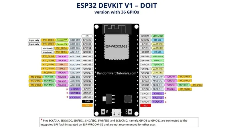
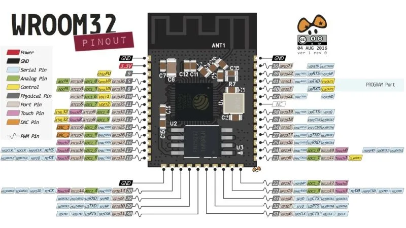
This ultimate guide will demystify the ESP32 pinout for popular development boards like the ESP-WROOM-32. We’ll break down every pin, explain its primary and special functions, and show you exactly how to use them with practical wiring examples and code. By the end, you'll be confidently connecting sensors, displays, and modules to build advanced IoT applications.

“Mastering the ESP32 pinout is the key to unlocking the full potential of WiFi, Bluetooth, and dual-core processing in your DIY projects.”
Before we dive into the pins, let's review what makes the ESP32 so powerful:
The ESP32's GPIOs are highly configurable. This is both a strength and a complexity. The following guide is based on the common 36-pin ESP-WROOM-32 module found on boards like the DOIT DEVKIT V1.
Crucial: The ESP32 is a 3.3V device. Applying 5V to any GPIO will likely damage the chip.
Most pins are multifunctional. Their function is determined by your code. Note: Many pins have restrictions.
// Example: Read Analog Sensor (LDR on GPIO 32)
void setup() {
  Serial.begin(115200);
}
void loop() {
  int analogValue = analogRead(32); // Read from GPIO 32 (ADC1_CH4)
  Serial.println(analogValue);
  delay(500);
}
This is where the ESP32 truly shines with built-in hardware support for advanced protocols.
touchRead().
// Example: Read Touch Sensor (GPIO 4)
void setup() {
  Serial.begin(115200);
  delay(1000);
}
void loop() {
  int touchValue = touchRead(4); // Read from T0 (GPIO 4)
  Serial.printf("Touch value: %d\
", touchValue);
  delay(1000);
}
Certain pins must be at specific logic levels on boot to enter certain modes (like flashing). Do not use these pins with pull-ups/pull-downs or components that might hold them high/low on boot.
Using the LEDC library for smooth fading on GPIO 16 (any output-capable GPIO will work).
// ESP32 Fade LED with PWM (LEDC)
#define LED_PIN 16
#define PWM_CHANNEL 0
#define PWM_FREQ 5000
#define PWM_RESOLUTION 8

int dutyCycle = 0;
int fadeAmount = 5;

void setup() {
  ledcSetup(PWM_CHANNEL, PWM_FREQ, PWM_RESOLUTION);
  ledcAttachPin(LED_PIN, PWM_CHANNEL);
}

void loop() {
  ledcWrite(PWM_CHANNEL, dutyCycle);
  dutyCycle = dutyCycle + fadeAmount;
  if (dutyCycle <= 0 || dutyCycle >= 255) {
    fadeAmount = -fadeAmount;
  }
  delay(30);
}
You now have a comprehensive understanding of the powerful and complex ESP32 pinout. Start by experimenting with digital writes and analog reads, then move on to its unique features like touch pins, Bluetooth, and dual-core processing. The best way to learn is by doing.
Ready for your next project? Check out our other in-depth guides:
Comments
0